Raising Battery Charging Voltage on Toyota, Lexus, Mitsubishi, Nissan, Subaru, Ford
Raising Battery Charging Voltage on Toyota, Lexus, Mitsubishi, Nissan, Subaru, Ford
The popular slogan "Winter is coming" suggests the imminent arrival of a cozy, romantic, magical winter. For everyone. Article relevance: 2026.

Attention! It is recommended that you read the article carefully, from beginning to end, reading every word and understanding what you read. If something is unclear - terms, principles, ideas, bad jokes by the author - then close the page, curse the idiot author, and go like logbook posts with half-naked citizens. You do not need this modification.
The article applies to all Toyota and Lexus models that have an ALT-S fuse or a similar charging system with a regulator Sense (S) output: Camry V30/V40/V50, Highlander, Land Cruiser, Prado, RAV4 (before 2019), Lexus, Tundra, Corolla, Auris, Wish, and others.
Other car brands have similar charging systems. Fuse names and charging-system names may differ from Toyota's, but the essence does not change. The operating principle is the same.
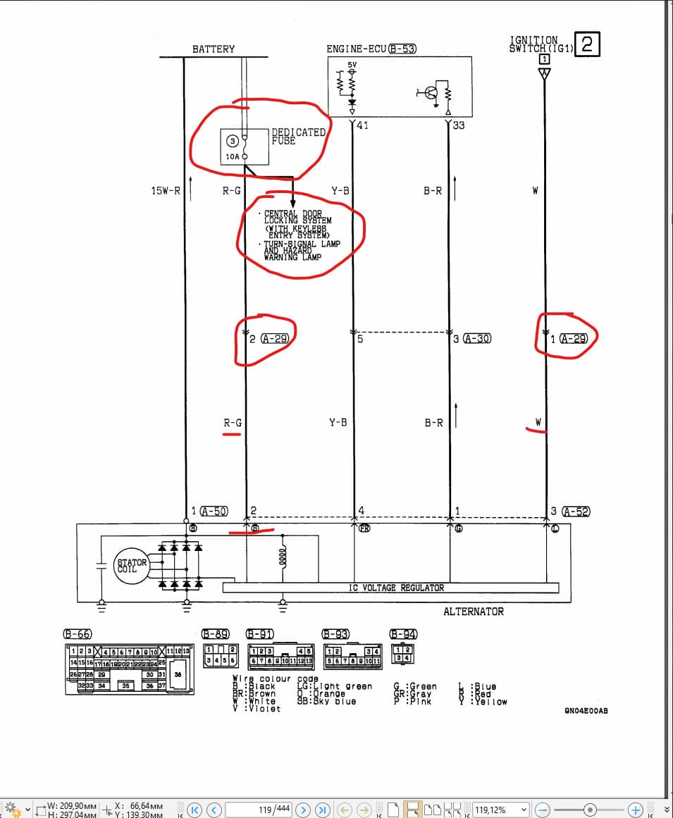
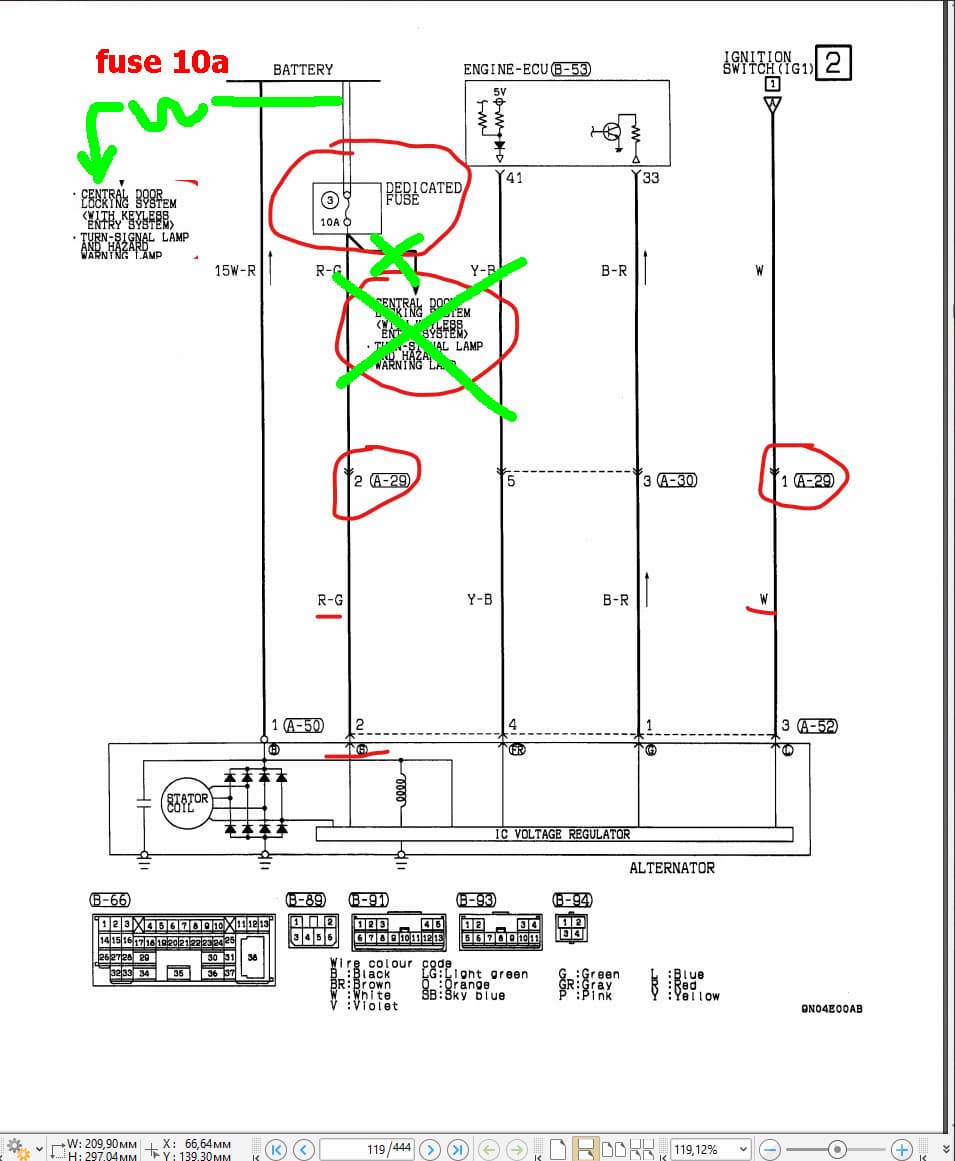
Some Ford and Nissan models (Almera, Terrano, Qashqai, etc.), KIA (Sorento, RIO), Hyundai (Santa Fe, Solaris) with the AMS charging system, Mitsubishi Outlander 3 from 2012-2018, Mitsubishi Outlander XL, Pajero, Mitsubishi Pajero Sport 2.4 DI-D Invite 6MT, many other Mitsubishi models, Subaru Forester (Subaru Forester SH5, third generation, Japanese right-hand-drive, fuse F16), Suzuki, Ford Focus 2 facelift, Ford Fusion, and possibly other brands.
Attention! I am not an electronics specialist for YOUR car. I know and understand only my own Toyota Camry (V50, 2012) well. On most other Toyotas (70%) this method will work. But not on all of them. I do not know exactly which brands it will or will not work on. Look at the wiring diagram for your own car and make your own decision. Do not ask me these questions! Any other car, even a very similar one, is a dark forest, hell, and 404 Kazakhstan Pakistan to me. I do not understand any other car (and do not want to) except my own. I cannot give any clever advice specifically about YOUR car.
After starting the engine, when the car is cold, the alternator output voltage is 14.3-14.4 V. After warming up (after 5-10 minutes), driving, etc., the voltage drops to 13.5 V and fluctuates around 13.5-13.8 V. This voltage depends only weakly on load. The obvious dependency is only on the temperature of the alternator with its built-in voltage regulator. The hotter the alternator, the lower the voltage it outputs.
The voltage-versus-temperature algorithm itself is quite reasonable, but its implementation is not the most successful. In some cars, battery temperature is monitored and voltage is regulated based on it. But that is expensive and inconvenient: it requires a separate temperature sensor, the battery needs to be in a separate closed box, and so on. When the battery is cold, it receives higher voltage; when it is hot, lower voltage. In most cars they do it more simply: they monitor the temperature of the alternator with the voltage regulator.
The problem is that the alternator heats up much faster than the battery and starts limiting voltage earlier than the battery needs. In cold weather, the alternator heats up in 1-5-10 minutes, while the battery remains cold, or even icy, after 2-3 hours. A hot alternator will output 13.2 V. At that voltage, a cold battery is clearly undercharged.
If you look at proper industrial and hobby battery chargers, full-charge voltage is 14.8-15 V. Japanese cars do not output such voltages from the alternator. And this phenomenon is not considered a malfunction; Toyota technical manuals specify a range of 13.2-14.8 V. Specifically in my Camry, the range is 13.3-14.4 V. Clear undercharging.
The battery itself confirms this by the gradual fading of the green float indicator. It looks like this: if the battery is new, even with insufficient charge the green float will "glow" for about a year. The acid is fresh, not degraded, the lead plates have no degradation or sulfation, and the internal "strength" of a new battery has some reserve. But without a full charge, nature takes over. Gradual sulfation and degradation of the acid solution begin. Although sulfation is reversible, 13.5-14 V is completely insufficient for that "reversibility."
Without normal charging, after a year the green float will "go out" forever unless the battery is charged with an external charger. A freshly externally charged battery with a green float works in the car for a while - say, two weeks - then the green eye gradually turns black and goes out. Electrolyte density drops. The battery still starts the car, but not as briskly as one would like. If the battery is charged fully with an external charger, the cycle repeats.
By the way, about the green float. In theory, the green light should mean an electrolyte density of 1.27, which corresponds to a fully charged battery. In reality, the green float simply means density above about 1.2. That is, even a lit green light does not mean a fully charged battery at all. It just means the battery is still more or less young, or is trying to be. If the green float indicated strictly 1.27 and above, battery sellers would not be able to sell a single battery.
Why does Toyota chronically undercharge? I see the reasons as follows:
- Fuel economy? Less load on the alternator means less gasoline used. Well, doubtful.
- Excessive protection against overcharging and boiling. Concern for safety?
- The battery is a consumable item, and no advertising brochure promised to preserve it? Most likely.
- Possibly other reasons; I am not an expert. For example, extending bulb life. Lower voltage means they last longer.
My bulbs do not die because they are LEDs, but I feel sorry for the battery. This needs to be corrected.
After studying the diagrams, I realized that Toyota's voltage regulator differs little (actually not at all) from, say, a VAZ regulator.
Toyota diagram:
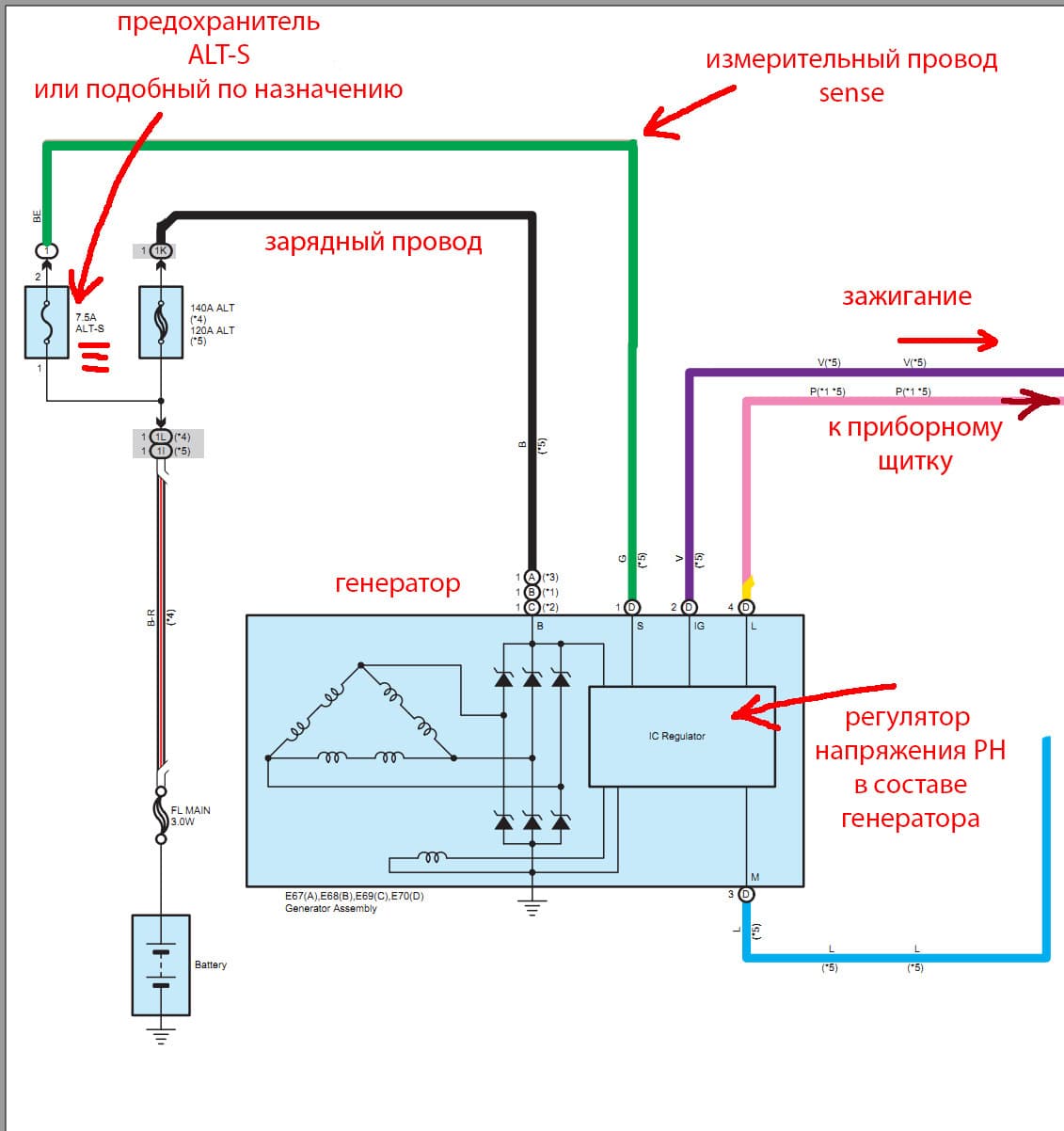
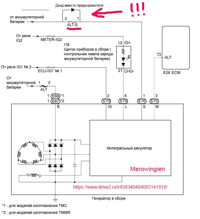
The general principle of such circuits is as follows: from the alternator to the battery PLUS there are two wires. One wire is thick, the main charging wire, through an 80-140 A fuse. The second wire is a measurement wire, through a 7-15 A fuse. On Toyotas, the first fuse is called ALT, and the second is called ALT-S. That is exactly the one we need. Similar circuits exist on a huge number of cars from other brands; the circuit and fuse names will be different.
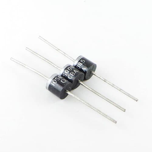
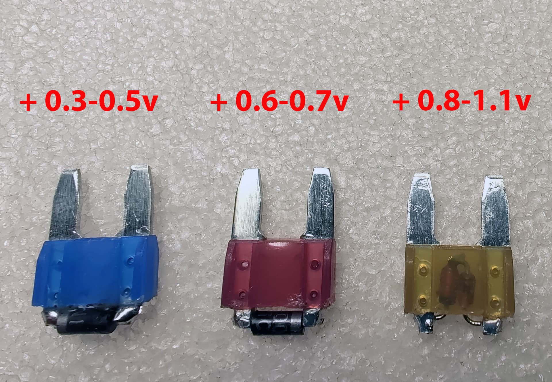
To raise the voltage (and therefore current) produced by the alternator, you need to make the voltage regulator think the battery voltage is lower than it actually is. For example, introduce a correction of 0.5 V. Or 0.7, or 0.4 - whatever you want. Toyota's voltage regulator receives battery voltage measurement data through the Sense output, which goes from the battery through the ALT-S fuse. The deception method suggests itself: insert a diode into the Sense circuit. The correction depends on the type of diode. Any ordinary rectifier diode gives 0.6-0.7 V; any Schottky diode gives 0.3-0.5 V. The diode can be spliced into a break in the Sense wire. But I did not want to cut anything, so I inserted the diode instead of the ALT-S fuse.
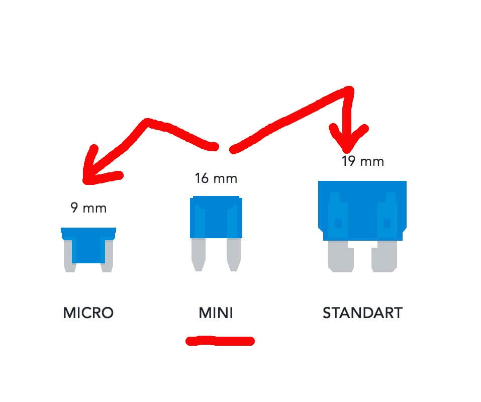
We make this construction from a BLOWN (!) MINI fuse with a diode soldered on top. Please note that the fuses must be good quality. Cheap supermarket fuses are not suitable. Practically all Chinese ones are unsuitable. Why? They are made of a rare Chinese alloy of clay and aluminum and cannot be soldered by normal means. They require special flux and solder. Rosin does not work on them. The body is nasty plastic that falls apart from the slightest heating.
Why a MINI fuse if my car uses MICRO fuses? Because a MICRO fuse is very hard to modify with a diode; it holds poorly and can fall off at any moment. A MINI fuse modifies easily and fits perfectly into a MICRO socket. Moreover, a MINI fuse fits perfectly into STANDARD fuse sockets, which are used in older Toyotas and VAZ cars.
By the way, the ALT-S fuse in the car is 7.5 A. The question arises: why such a large fuse rating on a measurement wire that goes nowhere except into the voltage regulator?
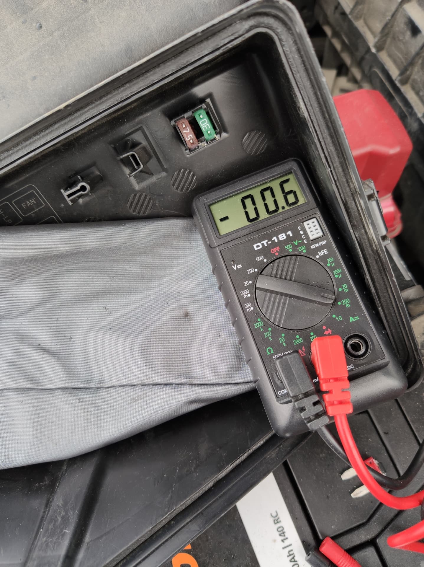
The real current in this circuit is about 6 mA, roughly 1200 times less than the fuse rating. A 1 A fuse would be more than enough there. Someone might answer: Japanese engineers are not stupid, they know what is there and why. Engineers, of course, know, but engineers do not rule; marketers do. They were the ones who figured out that a 7.5 A fuse is two cents cheaper than a 1 A or 5 A fuse. Since it makes absolutely no difference in this place what fuse is installed, they install the cheaper one.
This thought is indirectly confirmed by the fact that on different Toyota cars this fuse appears and disappears. For example: V50 2011-2014 has it; V55 2.0 2014-2015 does not (the fuse socket exists, but the fuse itself is absent; the ALT-S circuit goes directly from the alternator to the battery without any fuse inside the fuse box); V55 2016 and later has the fuse. Camry V70 does NOT. Toyota Caldina T19 has it; Toyota Caldina T24 does NOT. Prado 150 2009-2015 has it; Prado 150 diesel 2.8 from 2017 does NOT.
It is considered good practice to protect every circuit in a car with a separate fuse. But there is no need to fall into fanaticism. Some citizens hang a 1 A diode "on loose wires" and, "just in case," add a 10 A fuse. Common sense says that this fuse will never blow. In the case of, say, a crash with a mangled hood and many short circuits, the diode will ALWAYS blow first; it is effectively the fuse in this circuit. When installing a fuse with a diode, NO additional fuses are needed. Spare yourself the severe wire-spaghetti modification.
How does all this work in practice? Let us watch a short video. The starting conditions are: air, car, alternator, and battery temperature -2 C. The car has been standing in the garage for two days. We install the modified fuse with an ordinary diode instead of ALT-S. Start the car, idle. Using ordinary tweezers, we periodically short the diode, thereby "turning" the modified fuse into an ordinary stock fuse. Then we watch how charging voltage changes.
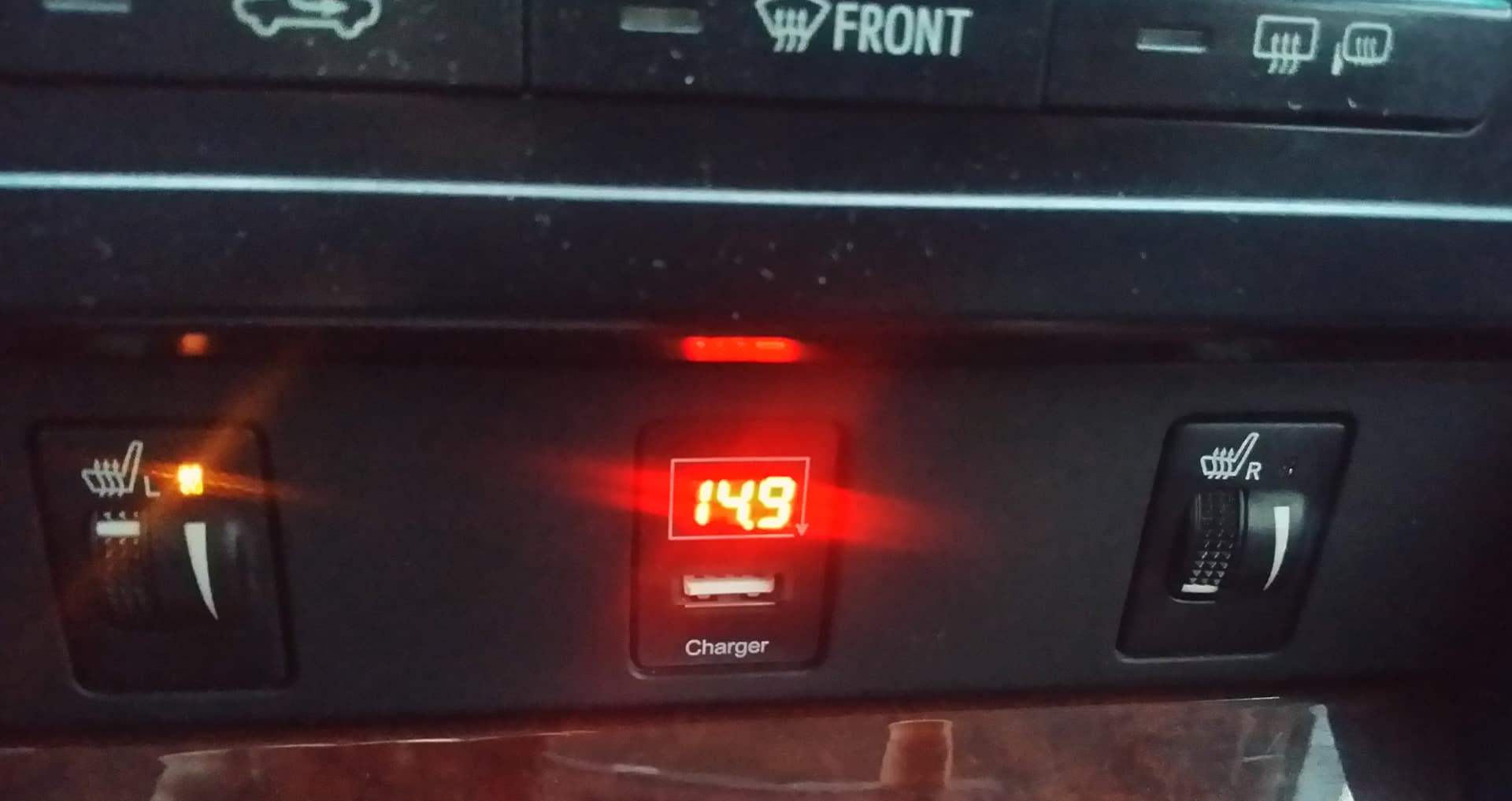
The voltage at the battery increases by the amount of the "deception": +0.6 to +0.7 V. That is exactly what we needed. Note that the numbers on the voltmeter on each car, and in different weather and alternator temperatures, will be different from my measurements on my car. What matters here is the difference with the diode versus without the diode.
"Smart" people and "electronics engineers" will choke on their sandwiches at this point and begin foaming at the mouth to prove that a battery is charged not by voltage, but by current. Of course they are right. But there is a big "but": charging speed.
Let me explain. A discharged battery charges perfectly well at, say, 13 V. In about a week or three (if you do not drive), it may charge to nominal. And if you do drive, it will never charge. By "nominal" I mean electrolyte density and the "green eye" that should light up. The battery also charges perfectly well to nominal at, say, 15 V - in about 6-8 hours, even while driving. All numbers are approximate, just to understand the principle.
The charging-current curve in a car looks roughly like this: the alternator supplies current to the battery, and the battery takes about 1-10 A. All these amps flow into the battery until the battery reaches the voltage set by the regulator, around 13-14 V. As soon as the set voltage is reached, the charging amps begin smoothly decreasing to minimal, near-zero values. Whether the battery has fully charged to nominal or not makes no difference to the alternator regulator. It knows nothing about that. It has a factory averaged algorithm and follows it.
With the diode, we move the upper voltage boundary at which the regulator starts reducing charging current - or, more precisely, at which the battery stops taking more. It seems that 0.4-0.7 V is not much. But it lets you put 30-40% more energy into the battery, faster, without going beyond the battery's electrical characteristics. For short winter trips, especially with heating and headlights, the diode is effectively saving the battery from an inglorious death after a couple of years of use. The diode does not make the battery better or more powerful; it is not a panacea. The diode simply prevents the battery from doing its job worse than it can and should, and significantly extends its life.
The following pictures, taken one second apart, show the voltage and charging-current change with and without the diode on a charged battery after three days of standing. The diode is switched on and off by a switch wired in parallel with it.
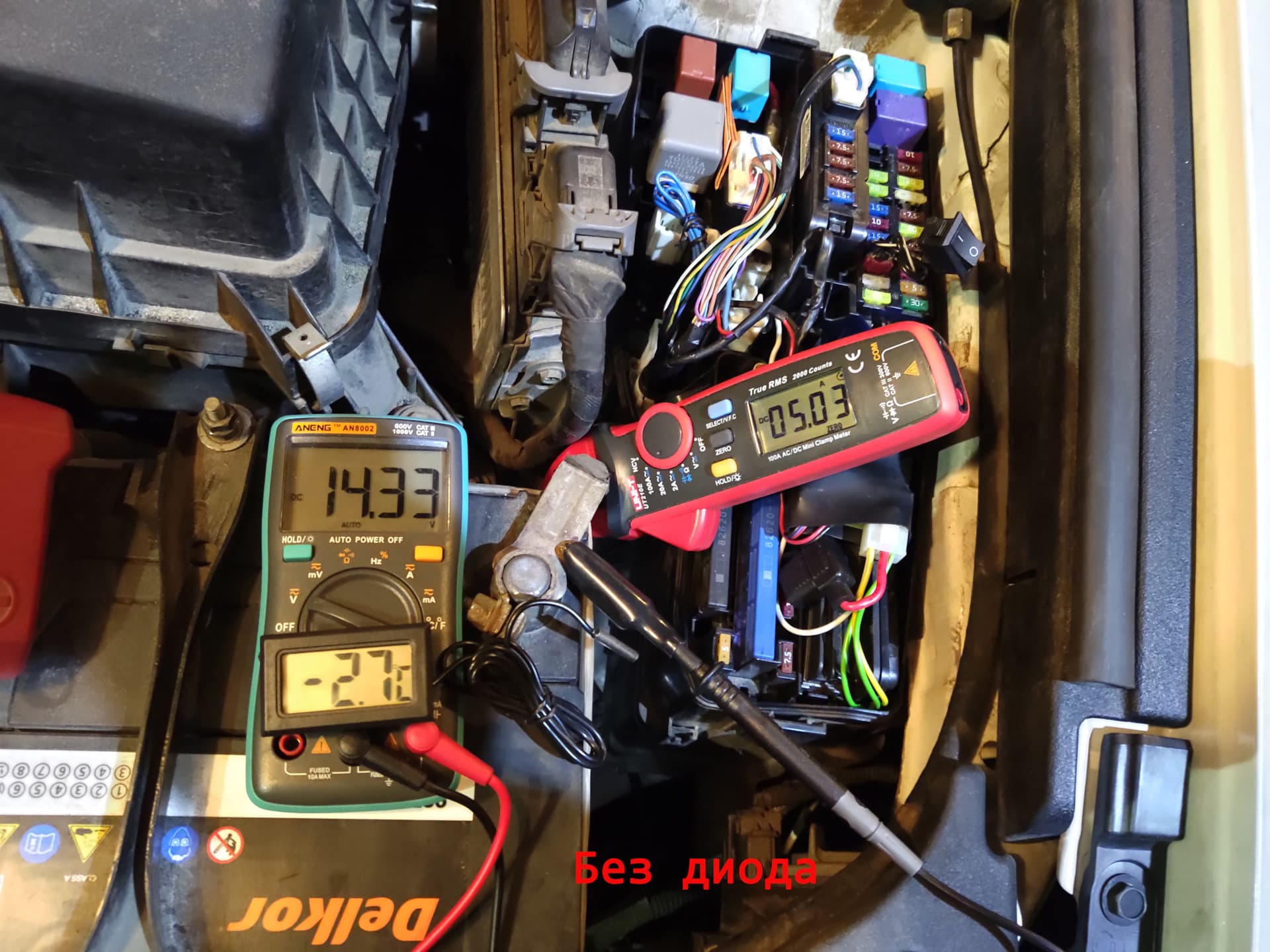
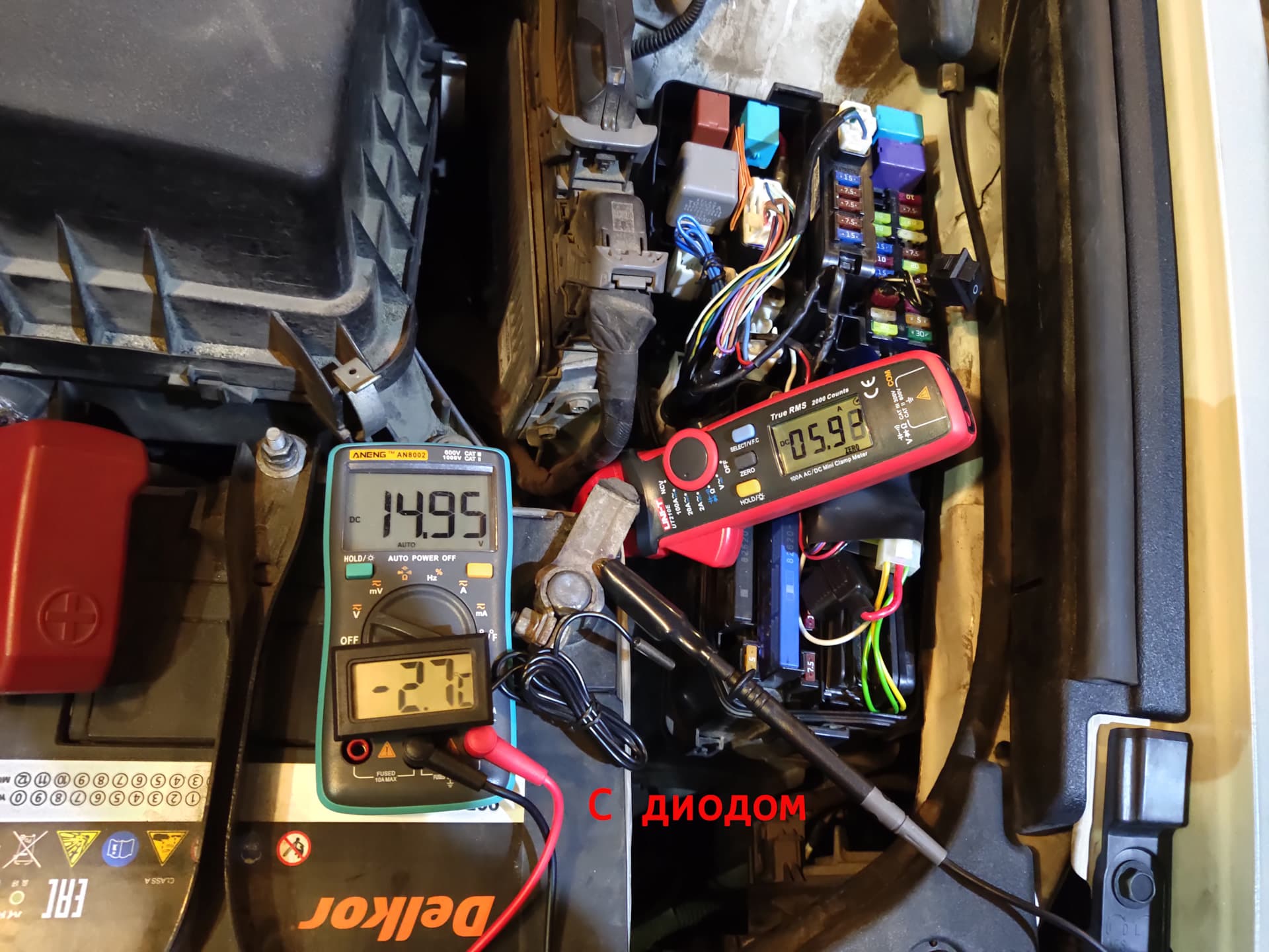
The difference in charging current when switching diode/no diode is clearly visible: 1 A (5.03 A to 5.98 A), and voltage difference is 0.6 V (14.3 to 14.9). With a discharged battery this difference will be even larger, about 3-4 A. More amps means faster charging and faster restoration of the battery's nominal state.
Note: these voltage numbers are only for a cold alternator! While driving, the alternator heats up quickly and the voltage will be lower; this is the regulator's thermal compensation at work. Diodes allow the voltage-regulator thermal-compensation thresholds to be shifted by the "deception" amount: 0.3-0.7 V. If the stock charging system gives 13.2-14.4 V from hot to cold, then with the diode this range will be 13.9-15 V from hot to cold.
In other words, after the engine starts, the alternator goes from "cold" to "hot" in about 5-10 minutes and remains there until the end of the trip or until the alternator cools. In stock form, with a "hot" alternator, charging voltage will be around 13.5 V on average, and the battery will never fully charge. Although, if you drive continuously from Moscow to Khabarovsk, maybe it will. "Stock" equals a half-dead battery. With the diode, average charging voltage will be around 14.2 V, and in about 12 hours the battery reaches close to full capacity. In reality you should not count on full capacity, but 90% is quite possible.
I foresee objections from citizens pointing to the fact of higher voltage and alternator wear. Hmm. I paid one and a half million for the car. That money went to Toyota. Now I want all of Toyota, its president, his vice president, the prime minister, all their wives, and all the Japanese people who made this Toyota to strain themselves for me, for my money. I want the whole car to strain itself, every screw and wire and especially the alternator, so that I feel good and comfortable for my money. And does anyone seriously believe that when the battery takes 1-3 A more current from the alternator than usual, the alternator is under significantly more stress? The alternator will not even notice that current against the background of all other consumption (up to 90 A).
As of today, my car has lived seven years with modified charging fuses. There have been no problems with the battery or electrical equipment. I wish the same to all of you.
Update 1
At the moment I can draw the following conclusions:
- By default, Toyota significantly undercharges the battery. In my opinion, the battery charge level is about 50-60%. You can drive, but not for long. Two or three years, then replace the battery. Sometimes longer, but rarely.
- If you drive rarely and little, and you have a Ca/Ca battery (this is practically all factory batteries), then install any rectifier diode (red fuse). You will get a voltage increase of +0.6-0.7 V. The regulator operating range will be roughly 14.9-15 V after starting and 14.2-14.3 V in charging operating mode. With this setup, the battery will charge to about 80-90%.
- If you drive often and a lot, you can install a Schottky diode (blue fuse). You will get a voltage increase of +0.3-0.5 V. The regulator operating range will be roughly 14.5 V after starting and 14.0 V in charging operating mode. The battery will charge to about 60-80%.
- At -30 C, the cold-start alternator voltage on a frozen car with an ordinary diode is 15.3 V. But it warms up fairly quickly: 5-10 minutes and it is 14.9 V, then everything continues as usual.
- All my conclusions are based on observing my car. On other cars, the data may differ somewhat.
- The number of batteries killed by undercharging is two to three orders of magnitude higher (two orders means 100 times) than those killed by overcharging. So charge, and you shall be charged.
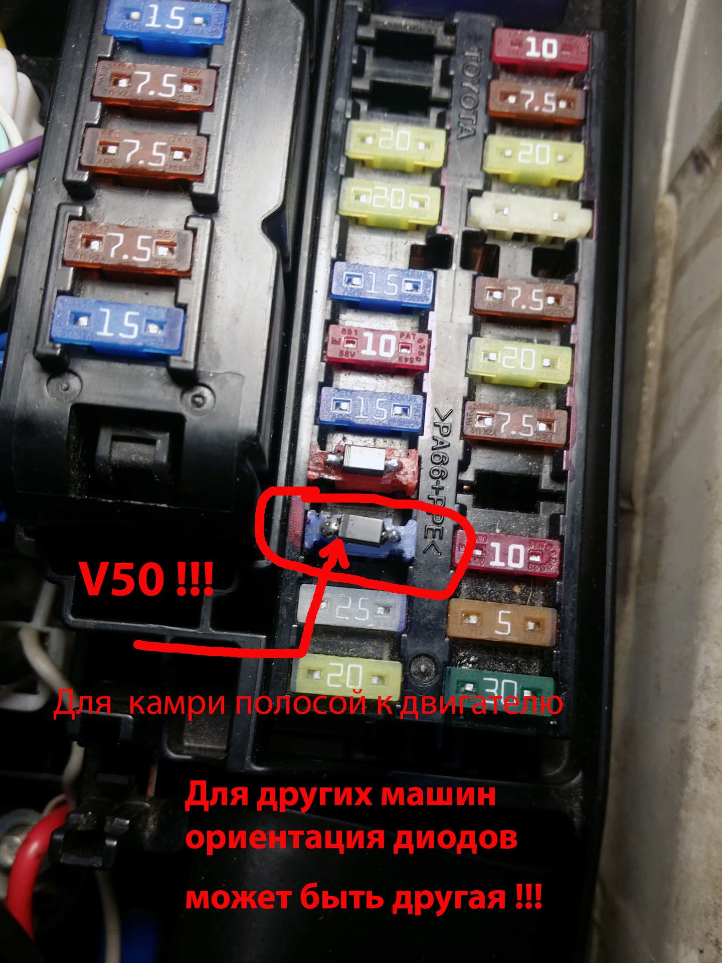
- The fuse with diode can be changed in one minute. Do not forget diode polarity. The stripe on the diode points toward the engine. This applies only to Camry V50. On other cars, diode orientation may be different. If a fuse with diode is installed incorrectly, the "alternator," "charge," or similar warning light will illuminate on the instrument panel.
- A fuse with diode will not resurrect a dead battery in one or two trips. It is best to first fully charge your discharged battery with an external charger for 1-2 days. After that, the fuse with diode will simply maintain the required charge level and prevent the battery from being undercharged, which is what we need.
Update 2
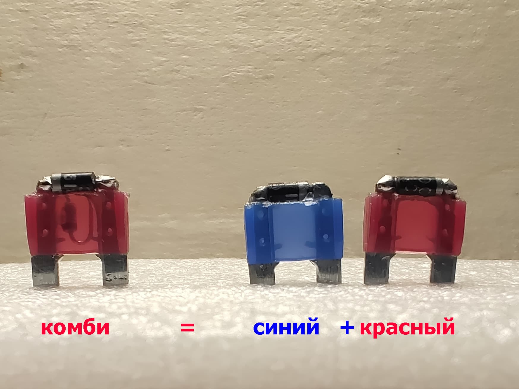
By popular request, I can send a set of three fuses: one with a Schottky diode, one with an ordinary diode, and one with combined diodes. This is for cases where people are too lazy to make them themselves, have no time, or have other reasons. The modified fuses can be found here; write messages or order immediately without messages if everything is clear and understandable to you.
I send fuses exactly like those in the photo and no others. This is the MINI format. Cars usually use MINI, MICRO, and STANDARD formats. They are partially compatible: a MINI-format fuse fits easily into MICRO and STANDARD sockets. But the opposite is not true: a MICRO fuse will not fit into a MINI socket.
Before ordering, make sure your car REALLY has this ALT-S fuse or another fuse with the same purpose! I mean LITERALLY make sure: open the hood, look at it with your eyes, touch it with your finger, listen to it with your ear, smell it with your nose, and lick it with your tongue for reliability. MANDATORILY perform the following test. With the engine off, pull it from the socket, start the car, look at the instrument panel; the battery "no charge" icon should light up. Turn the car off, insert the fuse back, start it, and the light should go out. Test passed. Your car, with high probability (carefully study the wiring diagram for your car!), may be suitable for this modification.
Most importantly, this modification is suitable only for a properly working car. If you install a fuse-diode on an old rusty wreck with a dead alternator and a faulty voltage regulator, it is like a poultice on a corpse.
And yes, by ordering modified fuses from me, you thereby confirm that you love cats, that you have read this article TWICE, and that you understand what this is, why it exists, and what results to expect from this exceptionally high-tech product.
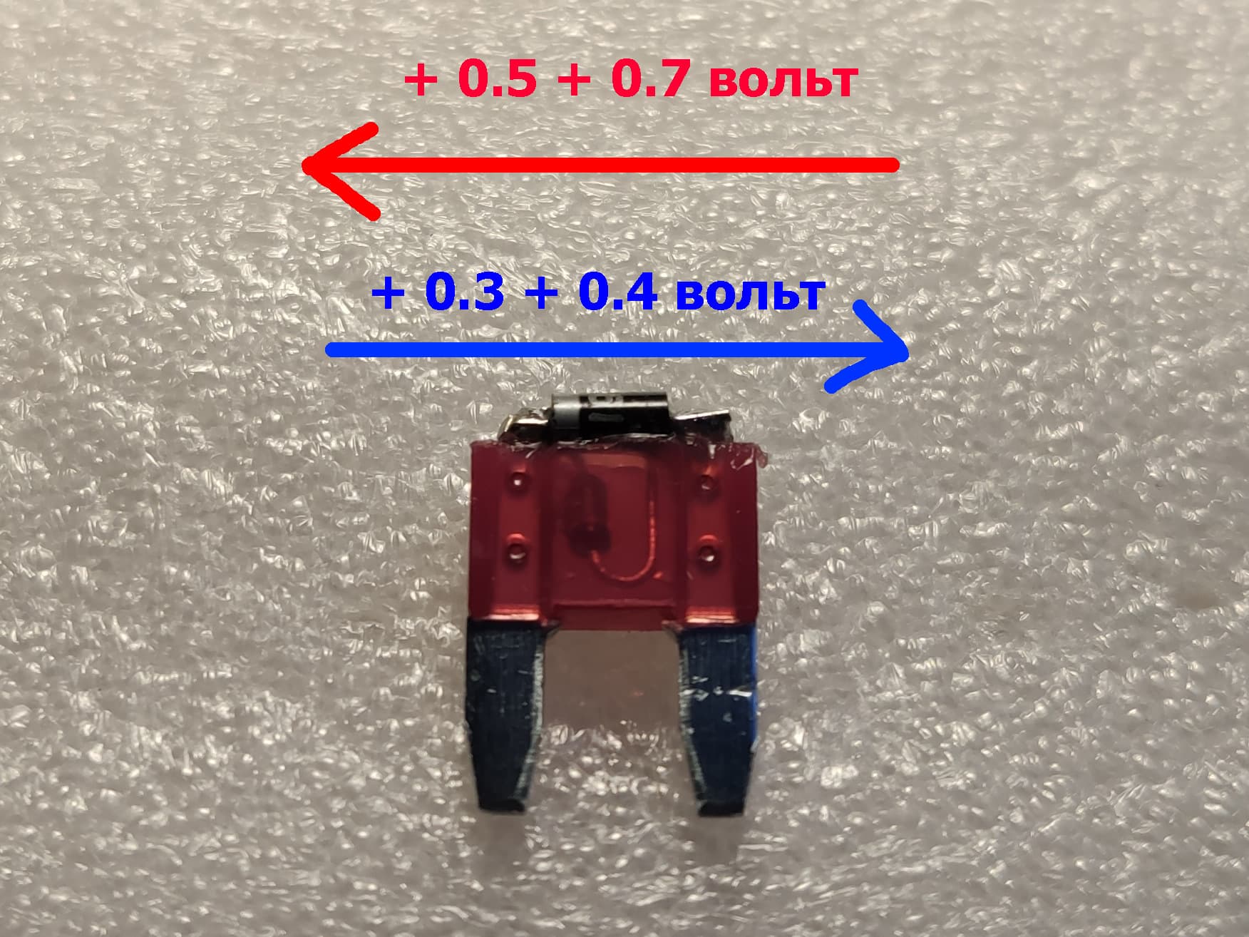
Addition 1 - for especially economical citizens, there is a dual combo-fuse option for two voltages. Perhaps someone will find this version more convenient. This one fuse replaces two fuses (red and blue). Depending on how it is installed in the ALT-S socket, the voltage increase differs. In one orientation of the fuse it will be 0.7 V; in the other, 0.4 V.
Addition 2 - there is no shipping outside our beloved homeland. None at all.
Update 3
The blue fuse with a Schottky diode gives +0.3-0.5 V. The red fuse with an ordinary diode gives +0.6-0.7 V. Some sharp-eyed citizens may notice that in the photo I have two ALT-S fuses installed next to each other in the car, "red" and "blue." Do not worry, only one participates in the work. The second is simply standing in an empty place so it does not get lost.
Update 4
Especially for the "tank drivers" and similar people. After reading or watching this article "diagonally," there is absolutely no need to ask me in private messages "which diode to install." Everything is written, photographed, and chewed through in the article. If something is still unclear, the best option is not to touch the car at all. Let it die its own death from old age.

Update 5
Especially for the absolutely impenetrable armored tank drivers. If, after reading the article and all imaginable warnings, you still ask one of the following questions:
- Is this safe?
- Will nothing burn out in the car?
- Can you guarantee everything will be fine?
- I did not read the whole article; explain quickly what to stick where.
- If I stick a nail into the engine, will it go faster?
- If I blow into the pipe, will a pineapple come out?
- Where do I find this ALT-S fuse in my car?
And other SIMILAR questions, you immediately go to the blacklist for a lifetime ecyh with nails. And this is not a joke.
Update 6
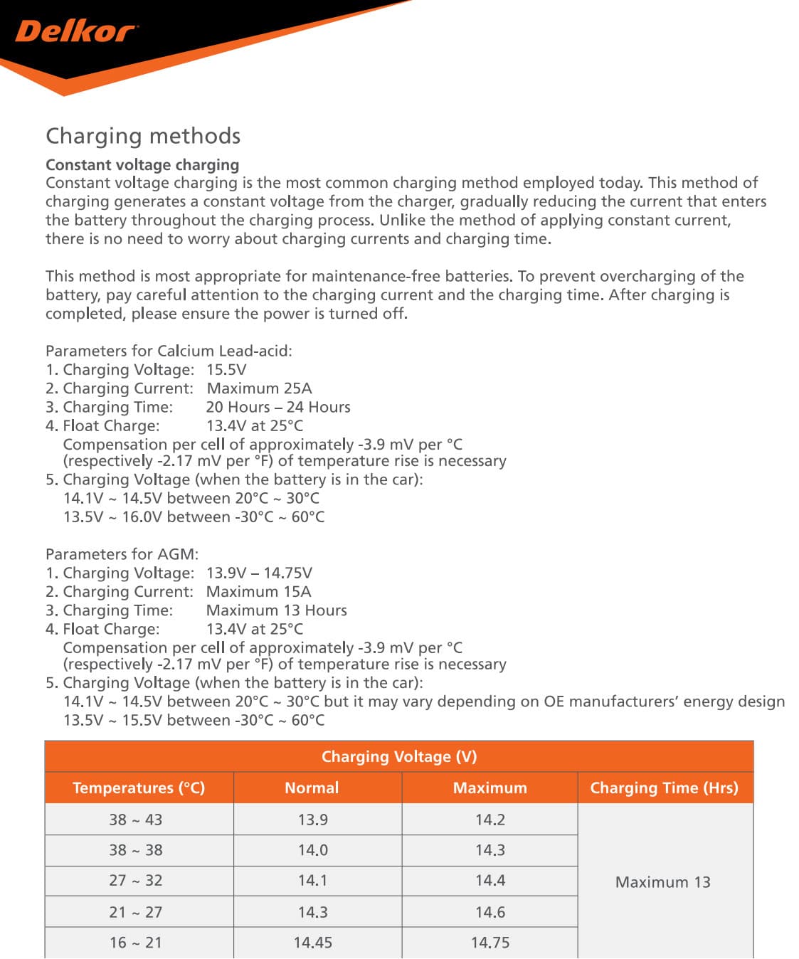
To settle the question of maximum permissible voltage for Ca/Ca batteries once and for all, I inform everyone: it is 16.2 V. Typical full-charge voltage is 15.5 V. Those citizens who categorically disagree with me on this question may go to crossed out battery manufacturers' websites for documentation, where everything above is written in black and white in English. For example, you can go to the site of the largest battery manufacturer, DELKOR, and find a document called Delkor_Battery_Manual_2019.pdf.
You can also peel the label directly from a MUTLU battery; instructions are glued on the side. There, in Russian in black and white, the FULL (100%) battery charge voltage is written: 15.6 V.
Update 7
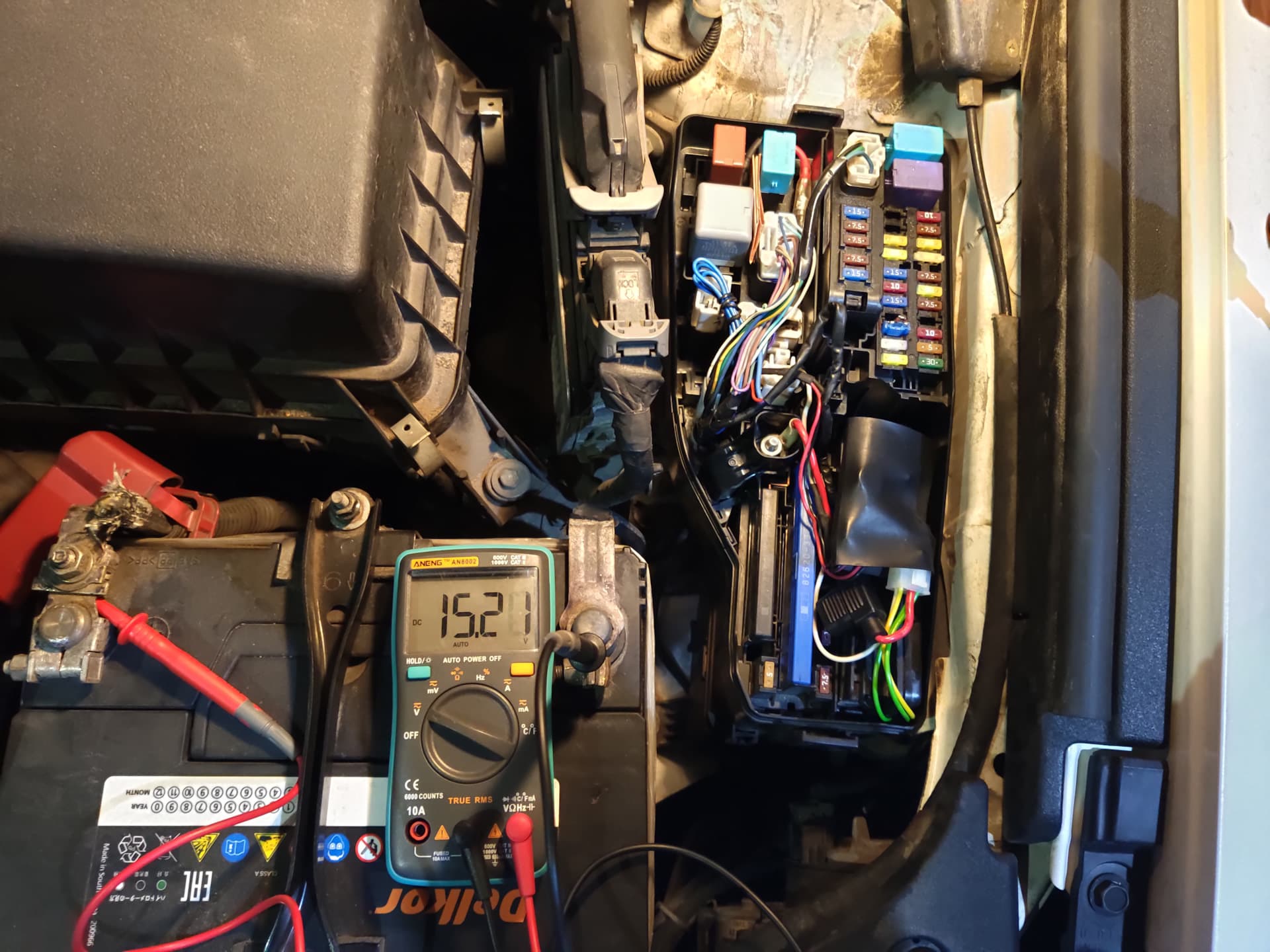
Can the voltage be raised even more? Hmm, theoretically yes. In practice, far from all alternators will withstand such brazen deception and output the required voltage. For example, the alternator on my car can output 17 V at 0 C. Probably at lower temperatures it can output even higher voltage. Is that safe for electronics? Doubtful. Toyota technical documentation clearly specifies a range of 13.2-14.8 V. Let us consider this range normal and absolutely safe.
There is probably another +0.5 V of reserve just in case, so let us consider up to 15.5 V conditionally safe. Anything higher is a big question (although it can be done; I tried it on my car). In other words, I can make a fuse that can try to deceive the regulator by 0.9-1.2 V. In general, installing this is not recommended, but if someone wants it, why not. We are reasonable people and answer for our own actions, right? Right? According to feedback from people, this option suits cars with a titanate battery, and "audio guys" also install this. I personally have not tested it on my own car (I am not an audio guy) and cannot say anything clever about it. But I can make a +0.9-1.2 V fuse (yellow).
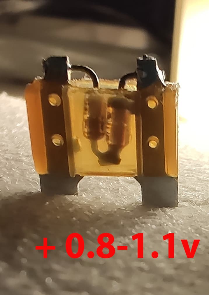
Update 8
What should you do in cases where the electrical diagram for your car has the ALT-S fuse and circuit, but in reality the fuse itself is absent - an empty or missing socket, for example Camry 55 from 2014? This problem can be solved with the help of an auto electrician. You need to find the ALT-S circuit wire that goes from the battery to the alternator and, in a convenient place, solder either a modified fuse with diode or simply a diode directly into a break in that circuit.
Update 9
Regarding KIA (Sorento, RIO), Hyundai (Santa Fe, Solaris), and other Korean cars with the AMS charging system: you can try deceiving this overly smart system with the same diode. Find the AMS fuse under the hood and install a diode instead. I have not checked or seen how all this will work, or whether it will work at all. But other people, Hyundai owners, have checked it. If they are not lying, it seems to work. In any case, all responsibility for decisions lies exclusively with the owner.
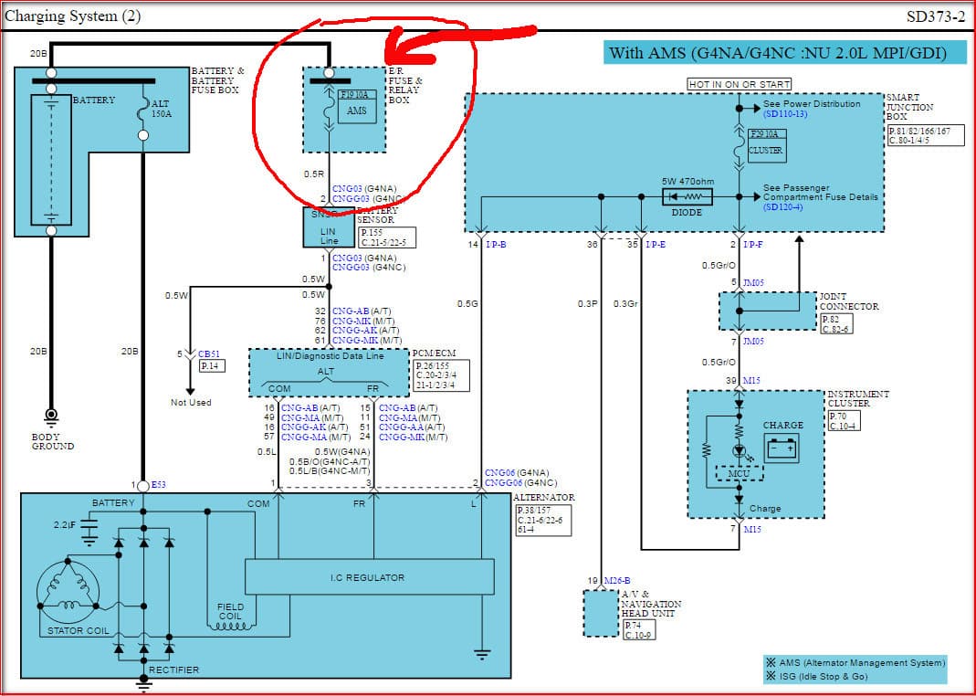
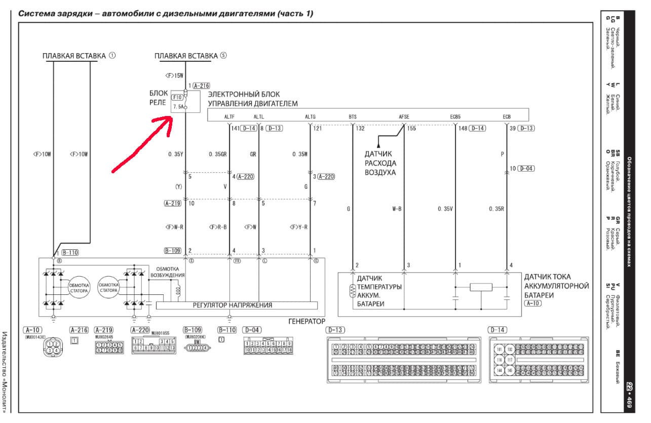
Regarding Mitsubishi Outlander 3 from 2012-2018, Mitsubishi Outlander XL, and similar models: look under the hood for the 7.5 A "generator" fuse and replace it with a diode.
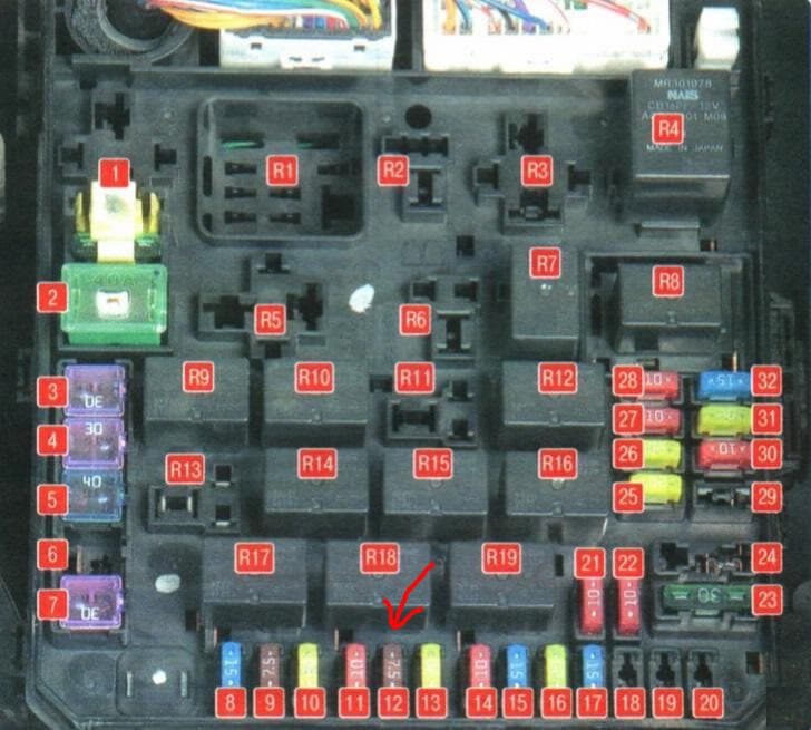
Attention! I personally have not checked all this in practice. Theoretically it should work. Owner feedback confirms this. The wiring diagrams for the alternator-control system have logic similar to Toyota's. On some newer Mitsubishis, it may be necessary to disable the built-in intelligent charging system (remove a fuse). Where it is and how to do it, I have no idea. I do not understand Mitsubishi. In any case, all responsibility for decisions lies exclusively with the owner.
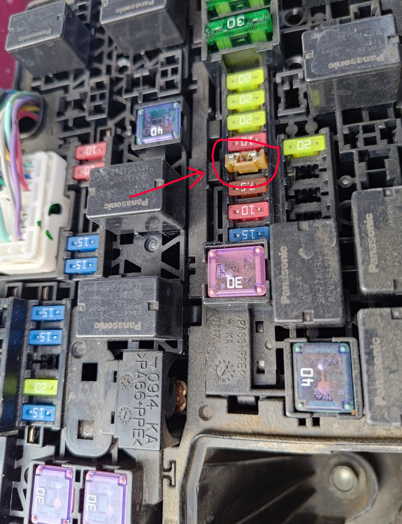
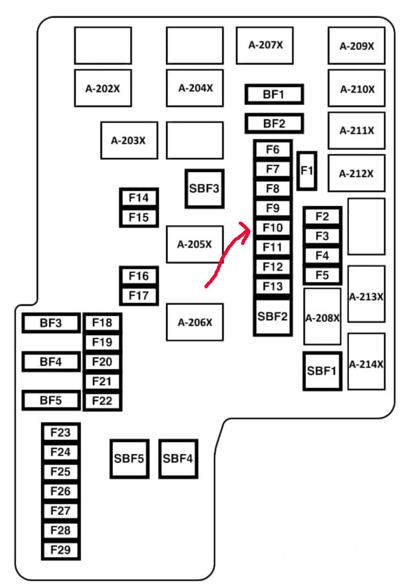
Mitsubishi Pajero Sport 2.4 DI-D Invite 6MT. Under the hood, find the 7.5 A "generator" fuse F10 and replace it with a diode.
Attention! On Pajero-Sport-like Mitsubishis, change fuses only with the car turned off. Otherwise, an error will appear on the instrument panel and the voltage will not change. So if an error appears, turn the car off, change the fuse/diode (or flip it over if the polarity is wrong), start the car - the error disappears and the voltage rises.
Update 10
What if you want to set a specific arbitrary voltage yourself? Well, brother, you cannot manage that alone; you need an assistant here. I admit that ordinary diodes may not be enough for some people. Fine. I have such a development, which I do not recommend to anyone at all because it has not been tested and may be unreliable. And the need for it is very questionable. But if someone needs it, that person will not be stopped, will they?
The device is inserted instead of the fuse and allows you to adjust the voltage addition with a knob in the range of 0.3-1.5 V. Whatever a person needs, that can be set. The voltage promises to be more stable than when using a diode; it will not jump plus/minus a volt depending on alternator heating. The device has a switchable voltmeter built in for quick voltage control. But there are several big BUTs:
- not every alternator will allow this (in the 1-1.5 V area);
- it does not look as neat as a simple modified fuse.
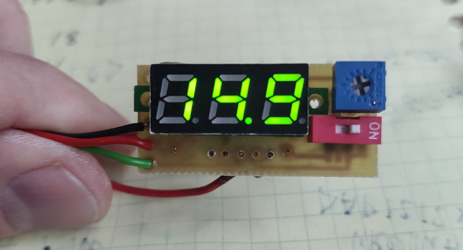
It exists as a single example; demand is being studied. In general, I do not yet recommend this product to anyone, simply because I have no data on its operability, reliability, or usability. It worked on my car, but my car loves me and forgives me everything. Whether it will work on any other car is absolutely not guaranteed, and I accept no responsibility for it. The photo shows the alpha prototype. There will also be beta and release versions.
Update 11
It may seem that the author is somewhat nervous. That is not true; I am kind and friendly. But it can be annoying when people ask the same questions in private messages a hundred times, even though I described them in great detail in this article. Why do people read diagonally or read nothing except the title? I tried hard, I wrote it… Some kind of mystery.